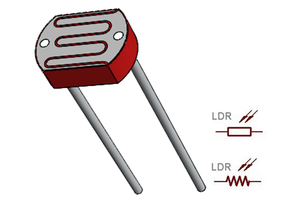
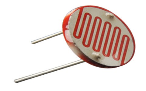
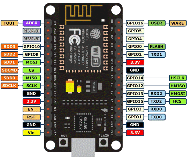
LDR INTERFACING WITH NODEMCU
In this project, we are interfacing LDR (Light Dependent Resistor) with the NodeMCU development board which has an In-built Wi-Fi Module (ESP8266) and used to increase and decrease the light based on its surrounding intensity levels.
Synopsis

In this project, we are interfacing LDR (Light Dependent Resistor) with NodeMCU development board which has In-built Wi-Fi Module (ESP8266) and used to increase and decrease the light based on its surrounding intensity levels.

Description


LDR sensor

LDR works as Variable resistance that depends on the light intensity, if the light intensity is less than the resistance value is more and vice-versa. This means when light is in dark it has high resistance and if the device is allowed to observe light then its resistance will be decreased drastically. LDR light sensor is used to detect absences and the Presence of light.


NodeMCU

A NodeMCU is a development board with an inbuilt Wi-Fi module in it. It is a basic and cost-efficient board to carry out projects using the internet of things. The NodeMCU has an ESP8266 microcontroller unit in it. The operation of this microcontroller is controlled with the programs used in Arduino thus making it very easier to use and also to learn basic IoT projects. This board has an inbuilt 2.4GHz antenna to receive Wi-Fi functions. This board has a memory of 4mb to store the data acting as ROM and 64Kb of RAM. This board operates at 3.3 volts and it is mandatory to operate the board at this voltage and not more than that as increasing the input voltage in this board may damage few GPIO pins (general input-output pins).


Pin Configuration

1. Vin: 3.3V can be provided at this pin as the supply to power on the board. This pin is used to power on the entire microcontroller.

2. GND: This pin is connected to the negative terminal of the battery.

3. RST: This pin resets the microcontroller and clears the memory.

4. EN: This pin is used to enable the operation of a microcontroller.

5. 3V3: This pin provides 3V output and this can be used to power up some sensor units connected to the microcontroller.

6. SD1, CMD, SD0, CLK: These pins are used in SPI communication, that is it is used to transfer the signals between two microcontrollers, Rx and Tx modules with asynchronous transmission.

7. SD3, SD2: These pins can also function as asynchronous transmission or as GPIO pins.

8. RSV: These are two reserved pins used by the microcontroller and cannot be used in connecting any external circuits to it.

9. A0: This microcontroller only has one analog pin for Analog communication. This A0 pin is used in analog signal communication.

10. GPIO 1 – 16: This controller board has 16 input-output pins which be used as input or output pin based on the programming.

11. GP10 1, 3, 13, 15: This microcontroller has 2 UART communication pins, RX0, TX0 (GPIO 1 & GPIO 3) and RX1, TX1 (GPIO 13, GPIO15).

Schematic


Code

int LDR = A0;
int LED = D1;
void setup()
{
  pinMode(LDR,INPUT);
  pinMode(LED,OUTPUT);
}
void loop() 
{
 int ldrval = analogRead(LDR);
 int mappedVal = map(ldrval,0,1023,0,255);
 analogWrite(LED,mappedVal);
}

Error message here!

Show Error message here!


Forgot your password?

Error message here!

Send OTP

Error message here!

Show Error message here!


Lost your password? Please enter your email address. You will receive a password you Need.

Send Error message here!


Back to log-in

Close